Three Wheel + IMU
A localizer that uses three odometry wheels and an IMU
Prerequisites
Ensure that three odometry pods are connected: two parallel to the length of your chassis and one perpendicular to the chassis. The Three Wheel + IMU AutoTuner will ask for the HardwareMap name of the motor port each encoder is plugged into, as well as the IMU HardwareMap name and Control Hub orientation.
Automatic Tuning
The Three Wheel + IMU AutoTuner can automatically determine the encoder resolution, encoder directions,
pod offsets, and turn multiplier for your ThreeWheelIMUConfig.
Add the Tuner
Add the tuner to your tuning file:
@Tuner
public static Procedure threeWheelIMUTuner() {
    return new ThreeWheelIMUTuner();
}
Import:
import org.firstinspires.ftc.teamcode.pedro.procedures.ThreeWheelIMUTuner;Open AutoTune
While connected to the Robot Controller, open the following address in your browser: http://192.168.43.1:10158
Select Octoquad Procedure.
Select Three Wheel + IMU Tuner.
Setup
The first screen asks for the three encoder motor-port names, the IMU HardwareMap name, and the Control Hub orientation.
The defaults are:
Left Encoder Motor Name:   lf
Right Encoder Motor Name:  rr
Strafe Encoder Motor Name: lr
IMU HardwareMap Name:      imu
Logo Facing Direction:     UP
USB Facing Direction:      BACKWARD
Important
The encoder names are the HardwareMap names of the motors whose encoder ports the odometry pods are plugged into.
Choose the Logo Facing Direction and USB Facing Direction that match the physical orientation of your Control Hub.
Encoder Resolution Identification
Enter the exact distance, in inches, that you will move the robot during each encoder resolution test.
The default is:
48If you leave this at 48, move the robot exactly 48 inches during each test.
Left Encoder Resolution and Direction
Press Continue, start the tuning OpMode, and push the robot forward the exact distance entered above.
When the movement is complete, stop the OpMode.
The tuner determines the left encoder resolution and direction.
Right Encoder Resolution and Direction
Press Continue, start the tuning OpMode, and push the robot forward the same exact distance.
When the movement is complete, stop the OpMode.
The tuner determines the right encoder resolution and direction.
Strafe Encoder Resolution and Direction
Press Continue, start the tuning OpMode, and push the robot left the exact distance entered above.
When the movement is complete, stop the OpMode.
The tuner determines the strafe encoder resolution and direction.
Coordinate Direction
Positive X is forward, positive Y is left, and positive heading is counterclockwise.
Left Pod Offset
Press Continue, start the tuning OpMode, and rotate the robot exactly 180 degrees counterclockwise about the robot's center of rotation.
Keep the center of the robot as fixed as possible.
When the rotation is complete, stop the OpMode.
Right Pod Offset
Repeat the same process for the right pod.
Rotate the robot exactly 180 degrees counterclockwise about the same center of rotation, then stop the OpMode.
Turn Multiplier Identification
Press Continue, start the tuning OpMode, and rotate the robot exactly 360 degrees counterclockwise.
Use a fixed reference point to make the full rotation as accurate as possible.
When the rotation is complete, stop the OpMode.
Applying the Results
After the tuner finishes, open the Java tab in AutoTune.
The generated ThreeWheelIMUConfig includes:
- Encoder HardwareMap names
- IMU HardwareMap name
- Control Hub orientation
- Left, right, and strafe pod offsets
- Forward and strafe encoder resolution
- Turn multiplier
- Encoder directions
Copy the generated configuration into Constants.java.
Manual Offset Tuning
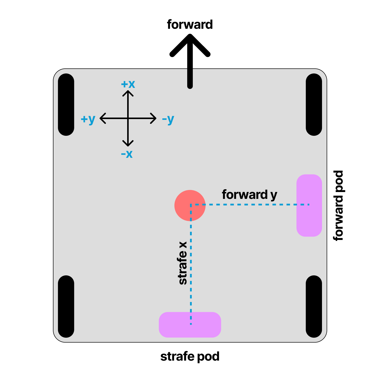
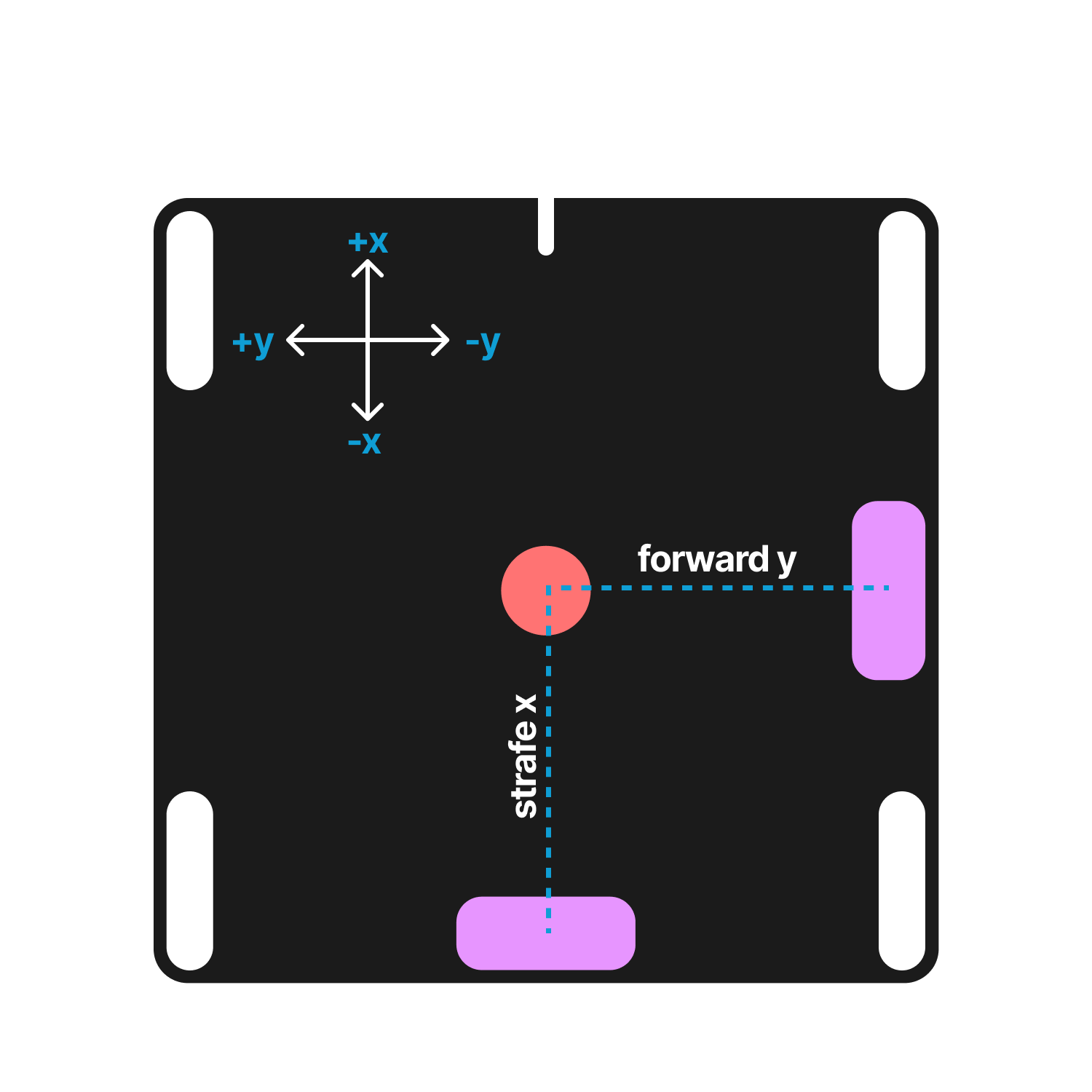
Offsets can also be found manually using the diagram below. Offsets are in inches.
Set your odometry pod offsets to define where they are relative to your robot's center of rotation.
Testing the Localizer
After applying the generated configuration, run the localization test.
Move the robot forward and verify that X increases.
Move the robot left and verify that Y increases.
Rotate the robot counterclockwise and verify that heading increases.
Note on ESD
If the robot suddenly changes heading, turns toward an incorrect angle, or develops large heading errors, the IMU may be affected by electrostatic discharge.
Consider grounding the robot with a grounding strap and reviewing the FIRST documentation on ESD.
If IMU interference cannot be resolved, consider using the non-IMU Three Wheel localizer instead.
Troubleshooting
If localization is incorrect, check:
- Encoder HardwareMap names
- Encoder directions
- IMU HardwareMap name
- Logo Facing Direction
- USB Facing Direction
- Pod offsets
- Encoder resolution values
If you have any problems, see the troubleshooting page.
Last updated on